CVD Diamond Heat Spreaders for High-Power Systems
Specify the complete heat path, not just a material value. Define the crystal route, geometry, surface, interface, joining method and verification before quotation.
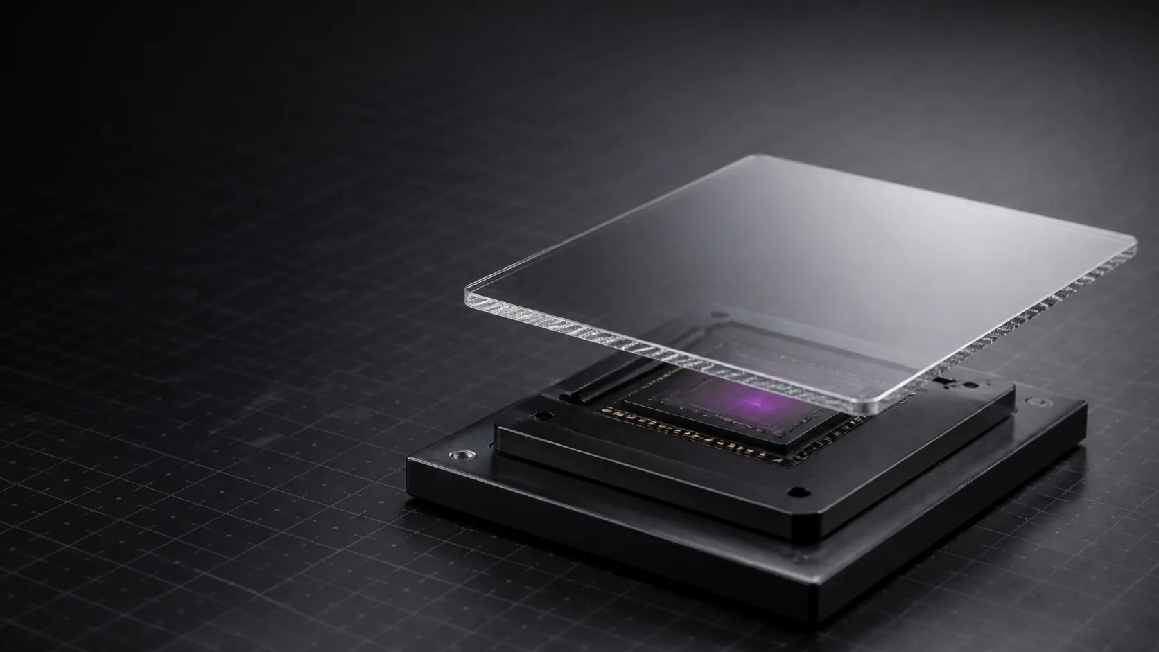
Define a diamond heat spreader from the full heat path.
A heat spreader moves concentrated heat into a wider area. It is one element in a complete thermal assembly that may also include interfaces, metallization, joints, a base, fins or cooling hardware.
Define CVD diamond by crystal route, geometry, surface, temperature, test method and boundary resistance. Quotation therefore starts with the complete heat path—not a context-free conductivity maximum.
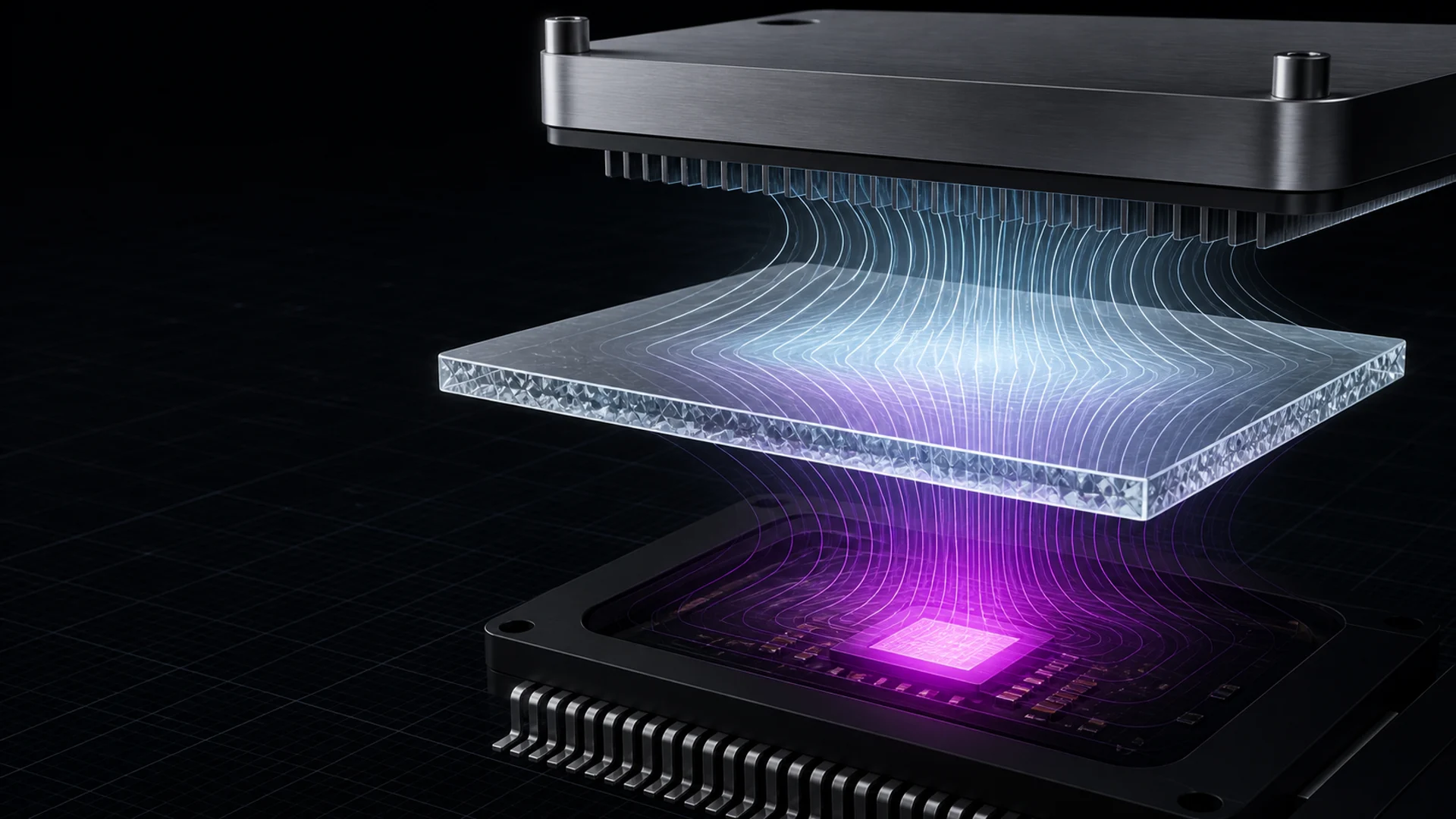
- 01Heat sourceHotspot · footprint · duty cycle
- 02Joining interfaceAttachment route · contact boundary
- 03CVD diamondCrystal route · geometry · surface
- 04Cold-side systemPackage · base · cooling boundary
Choose the device context.
Each scene changes the inputs that belong in the drawing, interface plan and acceptance review. The images are independent references, not DiamovaLab cases.

Cooling-system handoff
Define accelerator footprint, package constraints, cold-plate contact and the system boundary used to judge the material choice.
Licensed industry reference · not a DiamovaLab deployment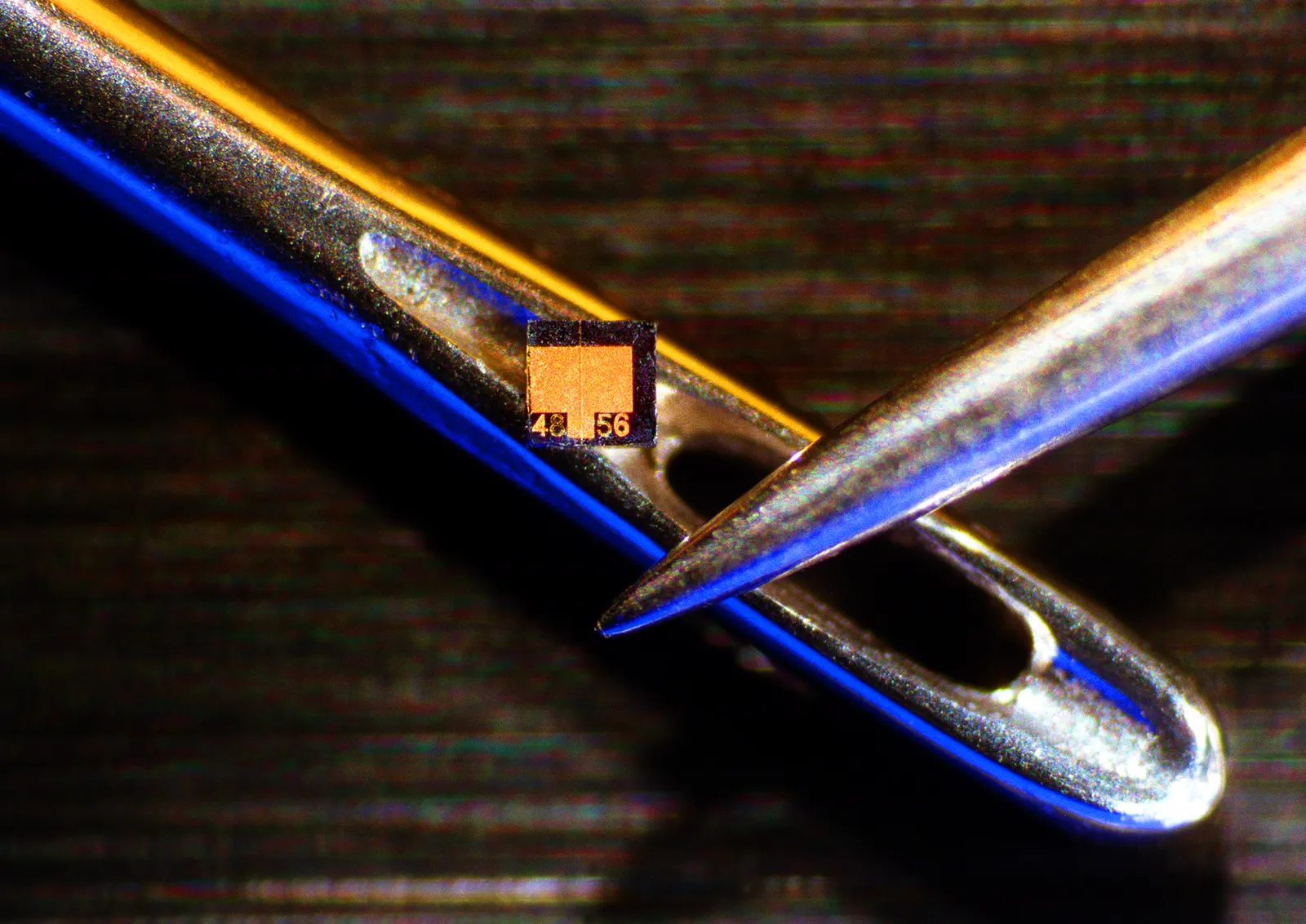
Optical-source heat removal
Record emitter layout, operating cycle, flatness, surface, joining method and the acceptance test expected for the part.
NASA/JPL reference · not a DiamovaLab product photograph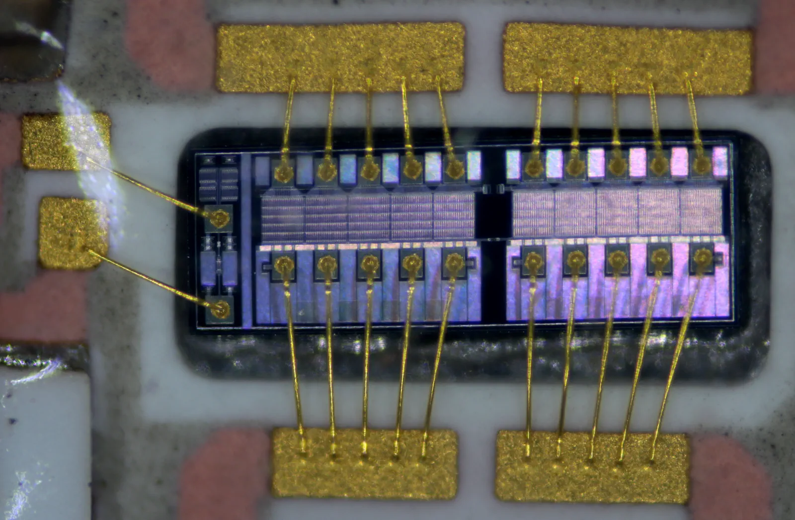
RF package hotspot control
Share active area, heat-flow direction, package geometry, electrical constraints and the attachment route for review.
CC0 industry reference · not a DiamovaLab device or case study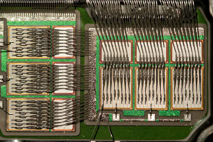
Compact package heat load
Map the device footprint, power envelope, target temperature, stack height and planned interface before defining the spreader.
Licensed industry reference · not a DiamovaLab customer projectDefine the part brief.
Each decision changes the drawing, interface plan and evidence that should accompany the proposed material. Available dimensions and performance values are confirmed for the specific project.
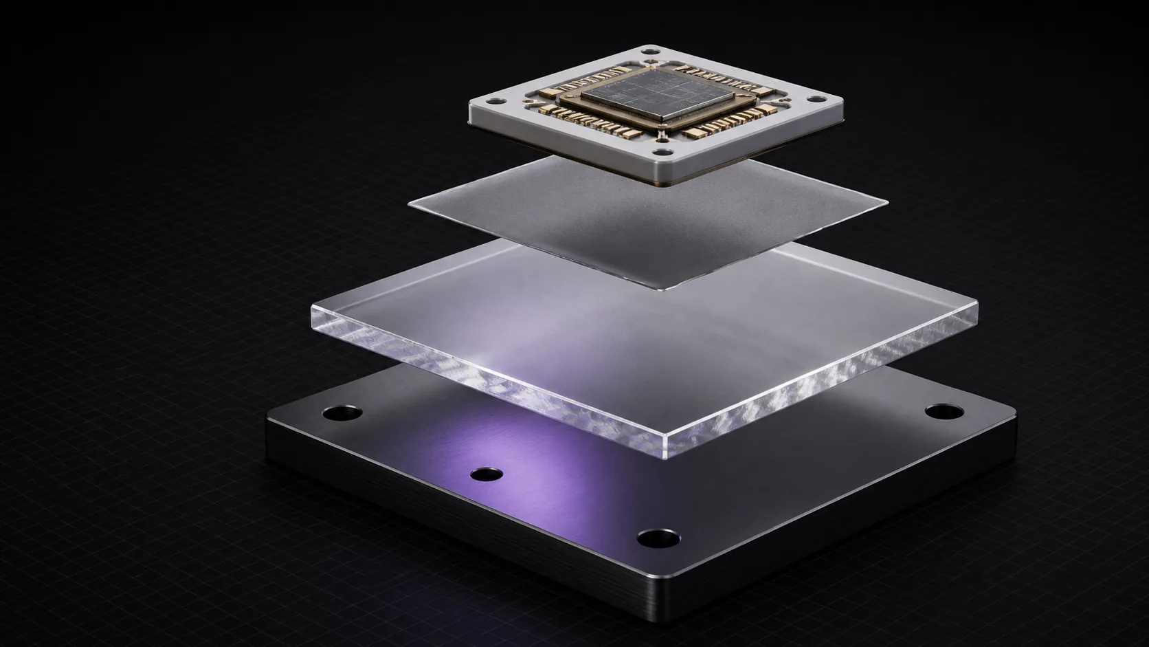
Four boundaries define the part.
Use the stack to separate the source, joining layer, diamond part and downstream cooling structure before a performance claim is reviewed.
- 01
Heat path and hotspot
Map the source, target temperature, footprint, heat-flow direction and surrounding package constraints.
- 02
Geometry and surface
Lock length, width, thickness, tolerances, flatness, roughness and edge requirements from the drawing.
- 03
Interface and verification
Define metallization or joining needs and the test method, temperature and acceptance evidence required.
Turn the drawing into a quote-ready scope.
Use the four groups below to keep buyer requirements, drawings and acceptance evidence attached to the same part definition before quotation.
01Thermal taskDescribe the system problem.
- Application
- Power device, RF package, laser module or other operating context
- Buyer-defined
- Thermal requirement
- Target plus temperature, direction and test or guarantee method
- Model or report required
02Part definitionLock material route and geometry.
- Crystal route
- Single-crystal, polycrystalline or open selection
- Client product matrix required
- Dimensions
- Length × width × thickness, drawing and edge details
- Client capability range required
03Surface and interfaceDefine what touches the part.
- Flatness and surface
- Flatness, bow or warp, Ra and polished-face requirement
- Inspection evidence required
- Metallization
- Stack, thickness, patterned area, tolerance and adhesion need
- Capability evidence not yet confirmed
- Joining
- Solder, braze, bonding or downstream assembly method
- Compatibility evidence required
04Commercial frameSet the review boundary.
- Commercial scope
- Sample or production quantity, required date and destination
- MOQ and lead time required
- Acceptance evidence
- Required report, sample identity, test method and approval rule
- Agree before quotation
Keep evidence at the right layer.
A material result does not by itself establish interface or assembled-device performance. Keep material, surface or joining, and device-level evidence attached to the correct project layer.
- 01
Material evidence
Crystal type, sample identity, dimensions, test direction, temperature, method and measured or guaranteed result.
- 02
Interface evidence
Surface condition, metallization stack, thickness, adhesion, solderability or bonding compatibility with defined test conditions.
- 03
Assembly evidence
Only a verified module build and device-level test may support claims about a finished heat sink, package or customer outcome.
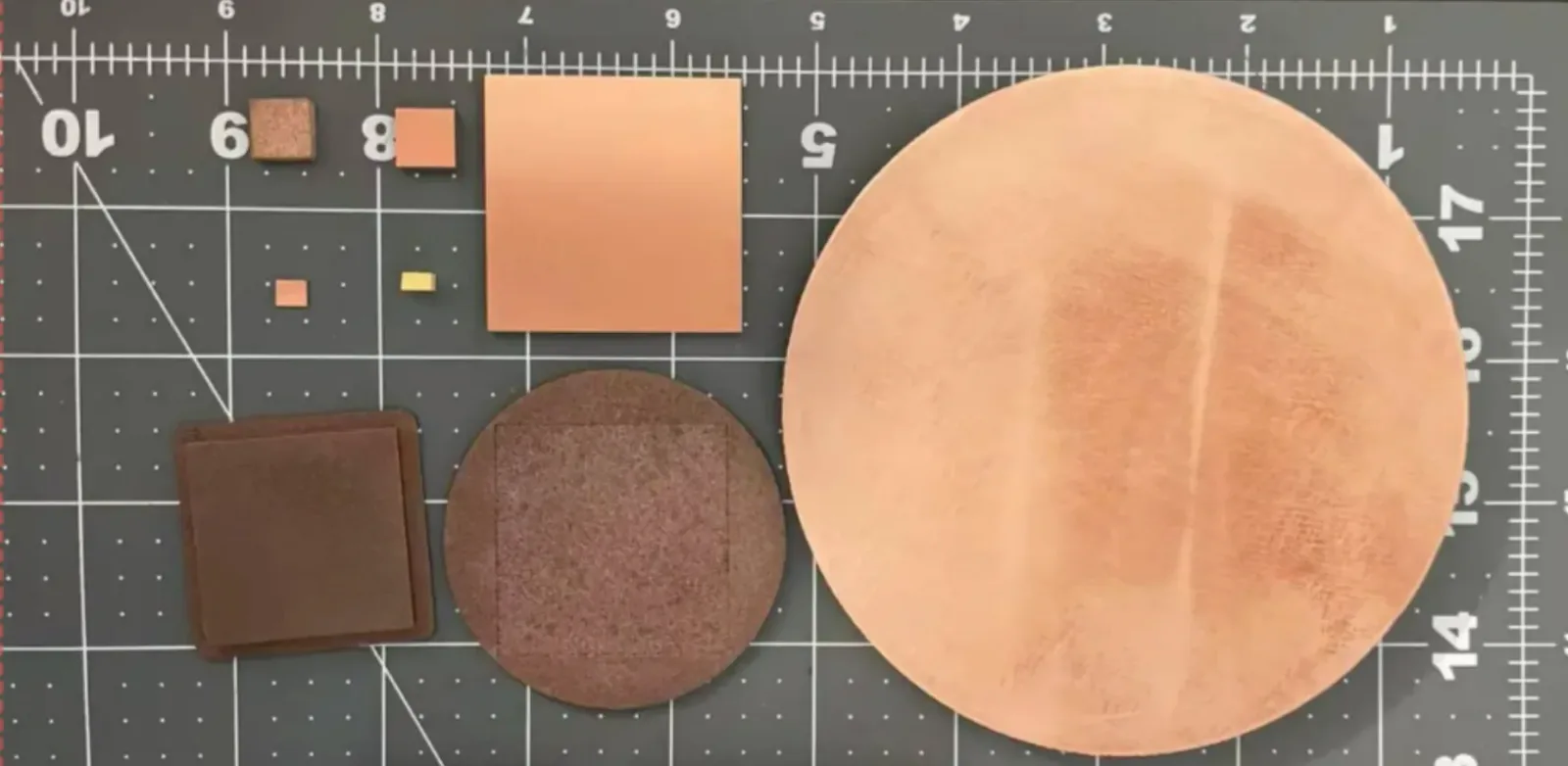
Two moving views and one range overview.
The clips show handling, an environment-exposure demonstration and an edge-profile view. They do not establish material construction, temperature, test method, process ownership or performance. The still image remains the broad form reference.
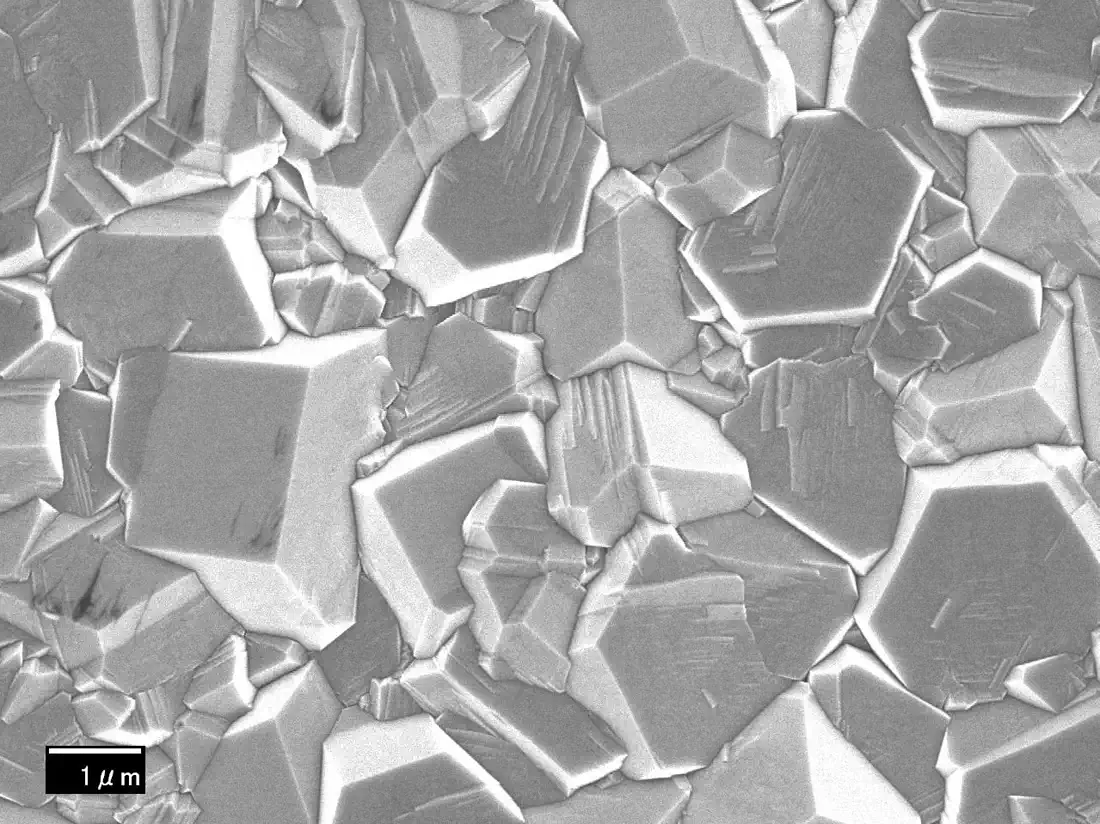
Material evidence
Crystal type, sample identity, dimensions, test direction, temperature, method and measured or guaranteed result.
Independent material reference · not a DiamovaLab test result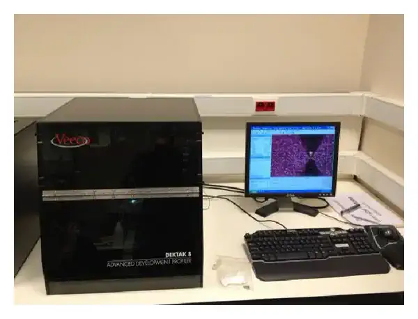
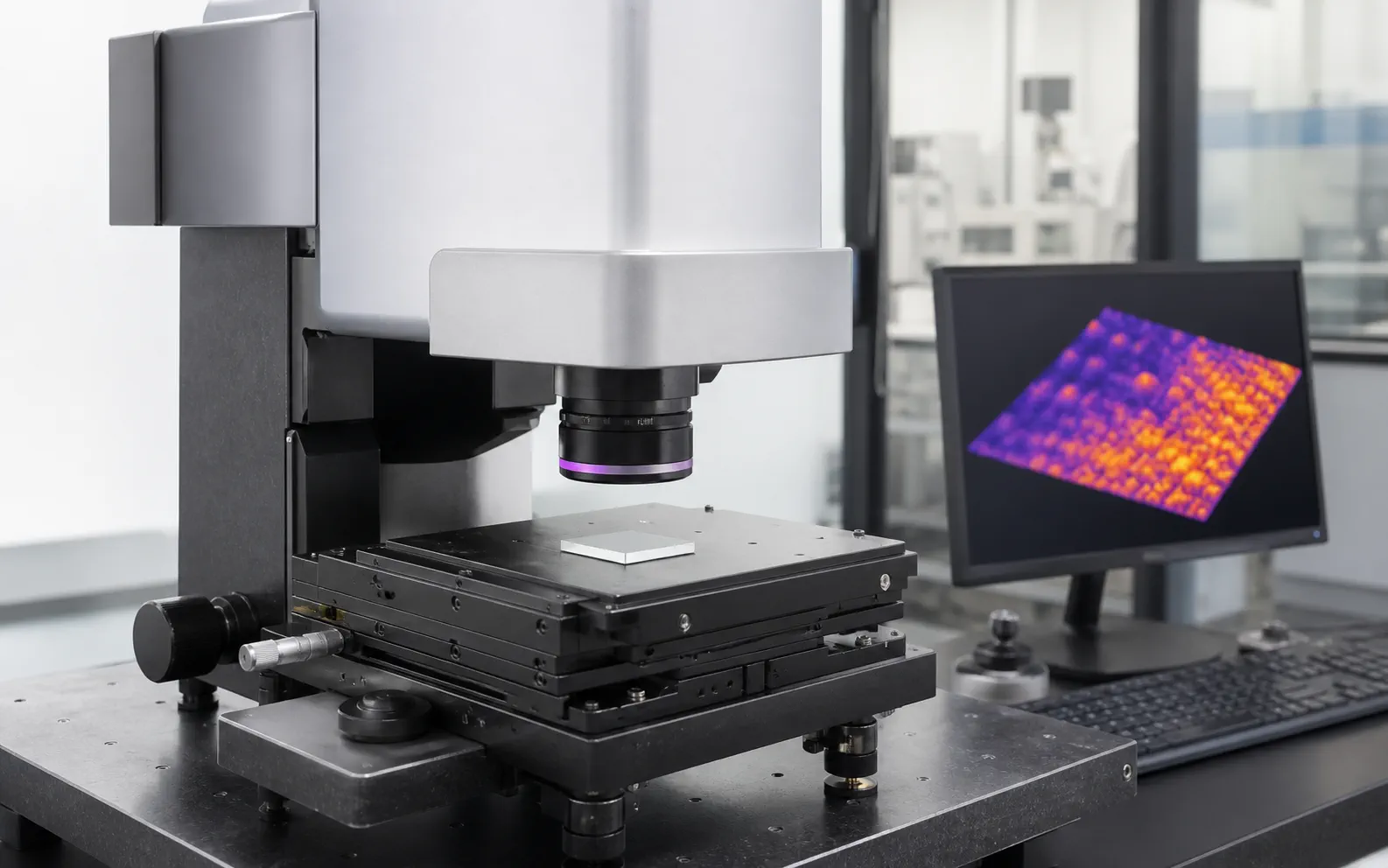
Interface evidence
Surface condition, metallization stack, thickness, adhesion, solderability or bonding compatibility with defined test conditions.
Licensed metrology reference · not a DiamovaLab laboratory or instrument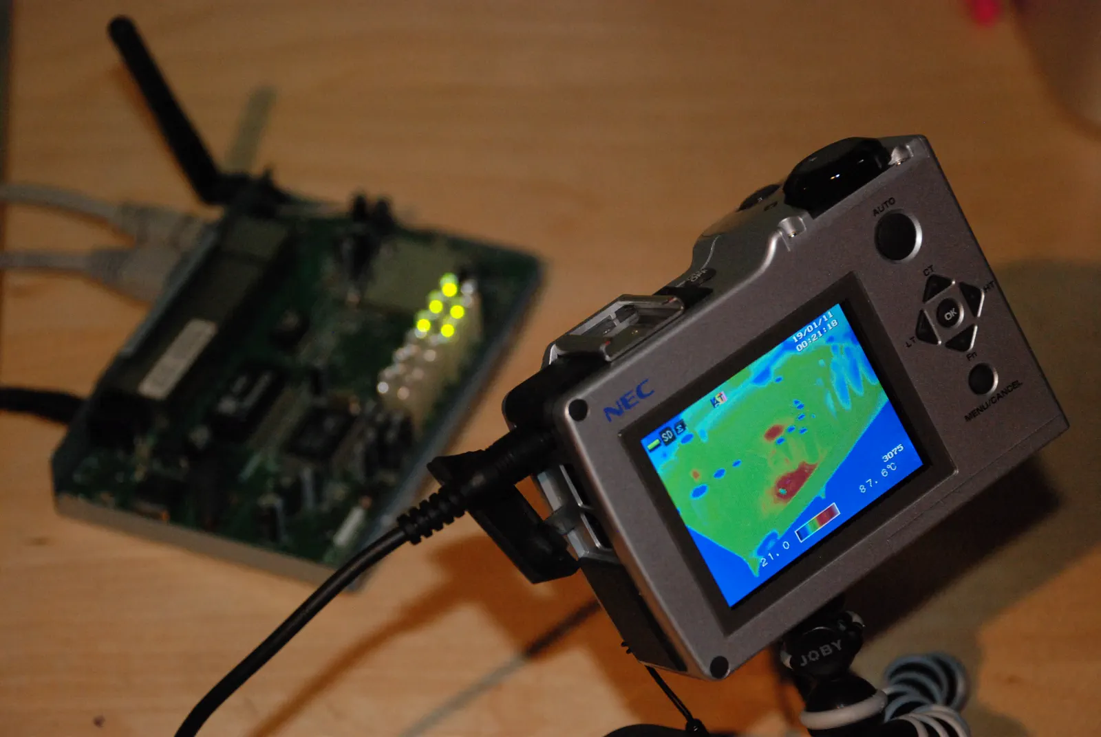
Assembly evidence
Only a verified module build and device-level test may support claims about a finished heat sink, package or customer outcome.
Public-domain reference · not a DiamovaLab module testPrepare a reviewable heat-spreader enquiry
Four review moments keep the requirement, evidence and commercial assumptions attached to the same part definition.
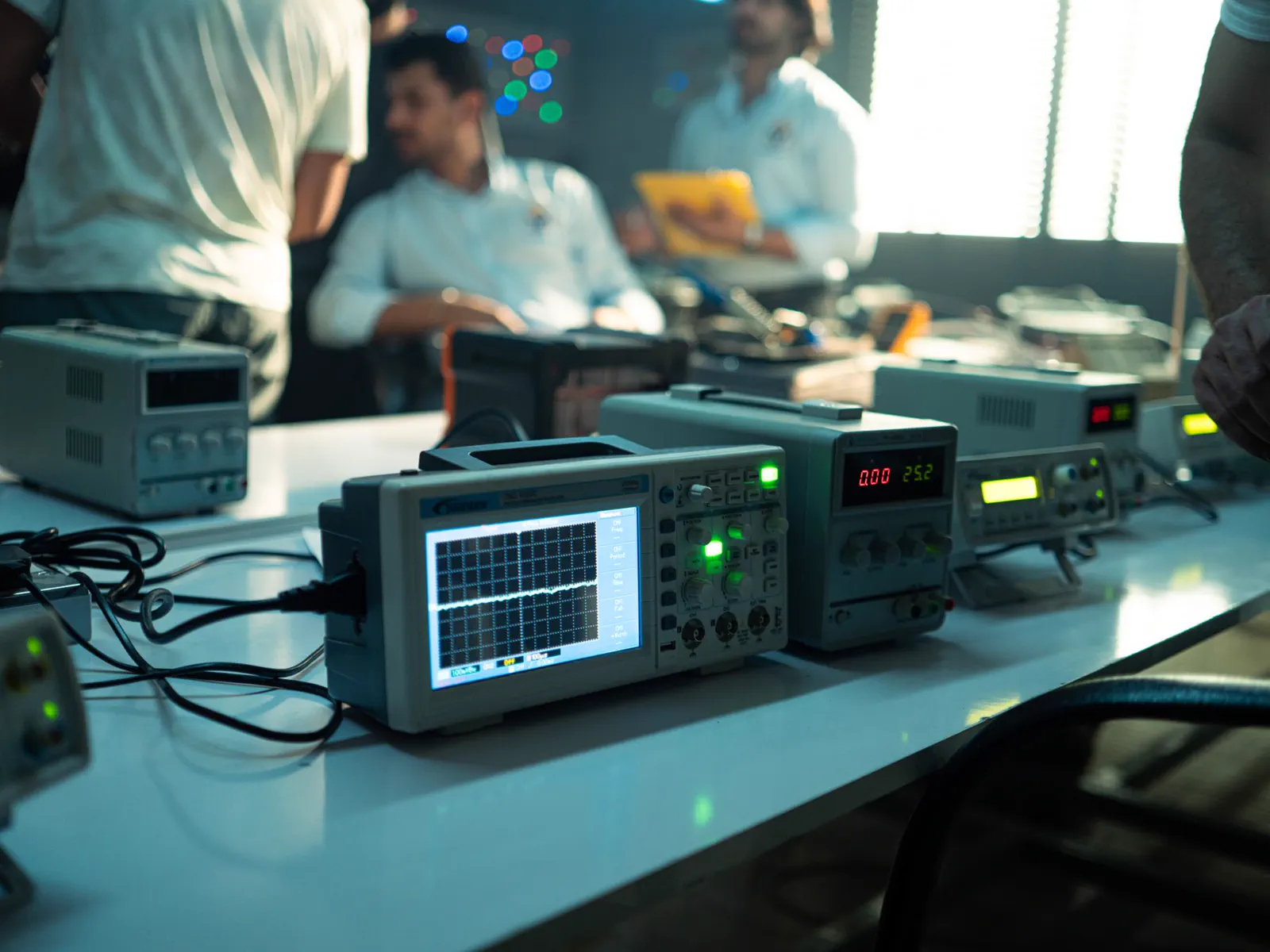
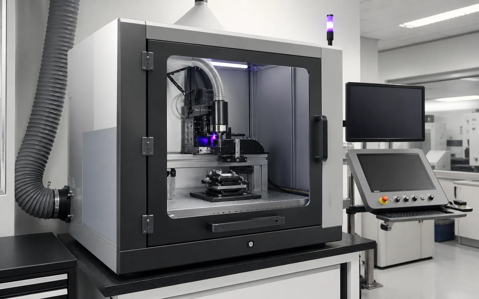
01Licensed reference context Map the source
Identify hotspot size, power envelope, current thermal path and the temperature problem to be solved.
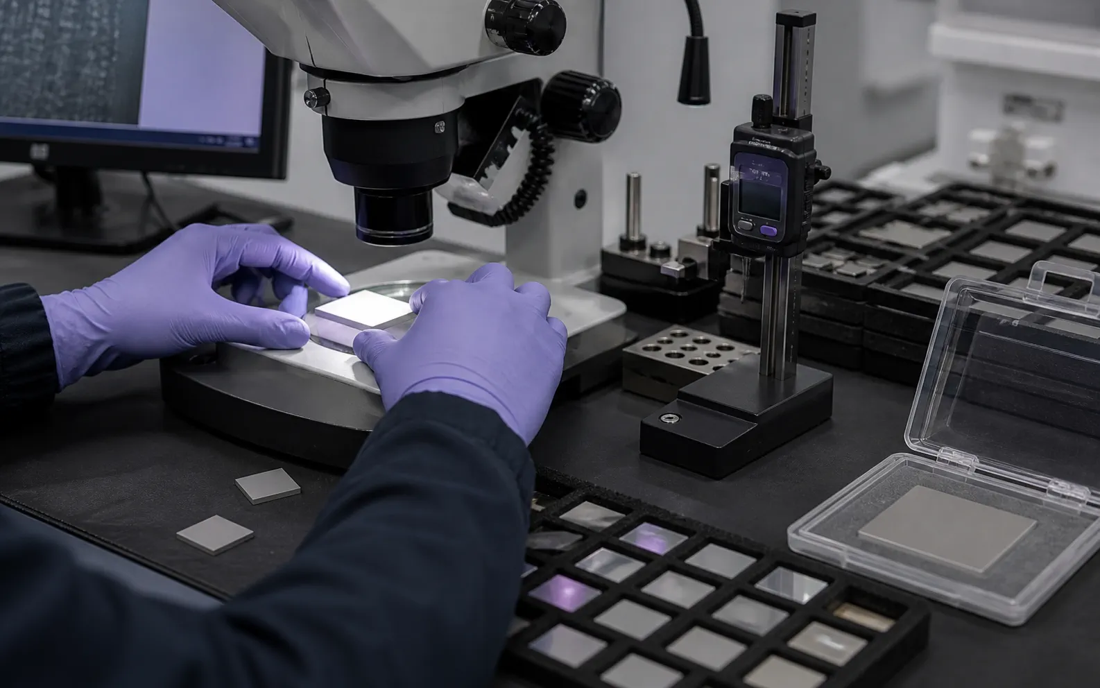
02AI illustrative context Attach geometry
Supply a drawing with dimensions, tolerances, surface, flatness and downstream assembly constraints.
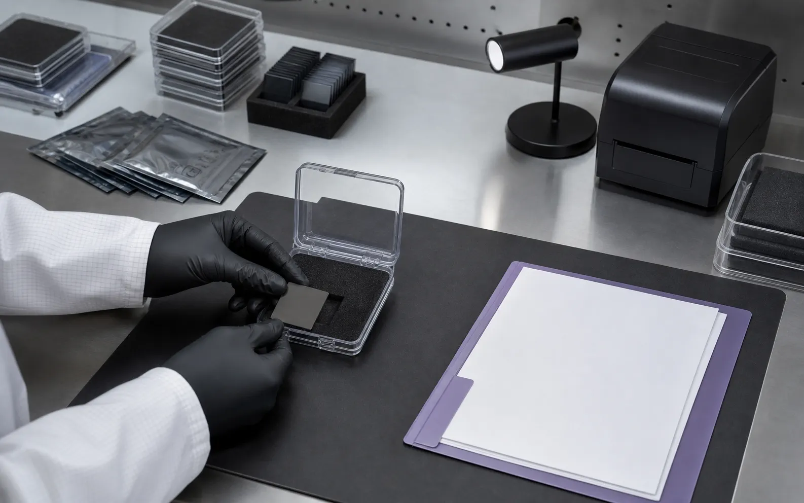
03AI illustrative context Define acceptance
State the thermal, dimensional, surface or interface evidence your engineering team expects.
04AI illustrative context Confirm commercial terms
A factual proposal can be completed after available material, sample policy, MOQ and lead time are verified.
Questions engineers and buyers resolve before approval
These answers keep the material, interface and finished thermal assembly distinct without hiding the terms buyers use to find this page.
01What is the difference between a diamond heat spreader and a diamond heat sink?
A heat spreader distributes heat from a concentrated source across a larger area. A complete heat sink usually adds structures that reject heat to air, liquid or another cooling system. DiamovaLab currently reviews the diamond spreader requirement rather than presenting a finished heat-sink module line.
02Does 2,000 W/(m·K) describe every CVD diamond heat spreader?
No. A conductivity value needs crystal type, direction, temperature, sample condition and measurement method. Device performance also depends on geometry and interfaces, so this page does not publish a context-free universal value.
03Can a heat spreader be supplied with metallization?
The project brief can capture metallization stack, thickness, patterned area, tolerance and joining requirements. Supply scope and supporting evidence are confirmed for the requested part before they are included in a quotation.
04What information reduces the first engineering review cycle?
Provide the application, heat-source footprint, dimensions, thickness, flatness, surface, interface or joining method, quantity, required date and the test evidence needed for approval.